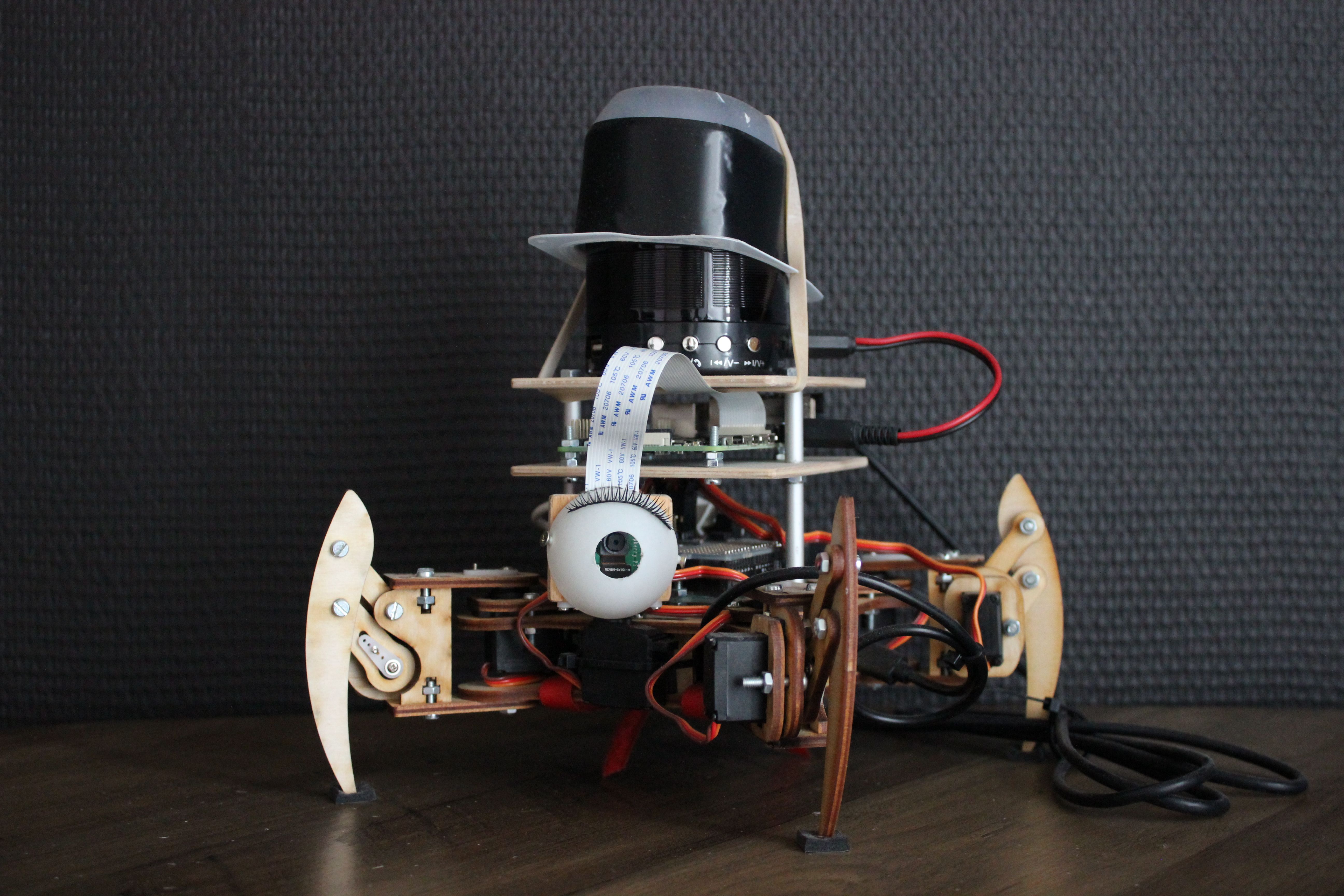
Make your own Quadruped Robot
By Eva Denys
2019-12-20
#Development
#Arduino Uno
#Raspberry Pi
Build your own Duke with this tutorial. Control with your phone, Alexa abilities, etc... Make making a quadruped robot fun!
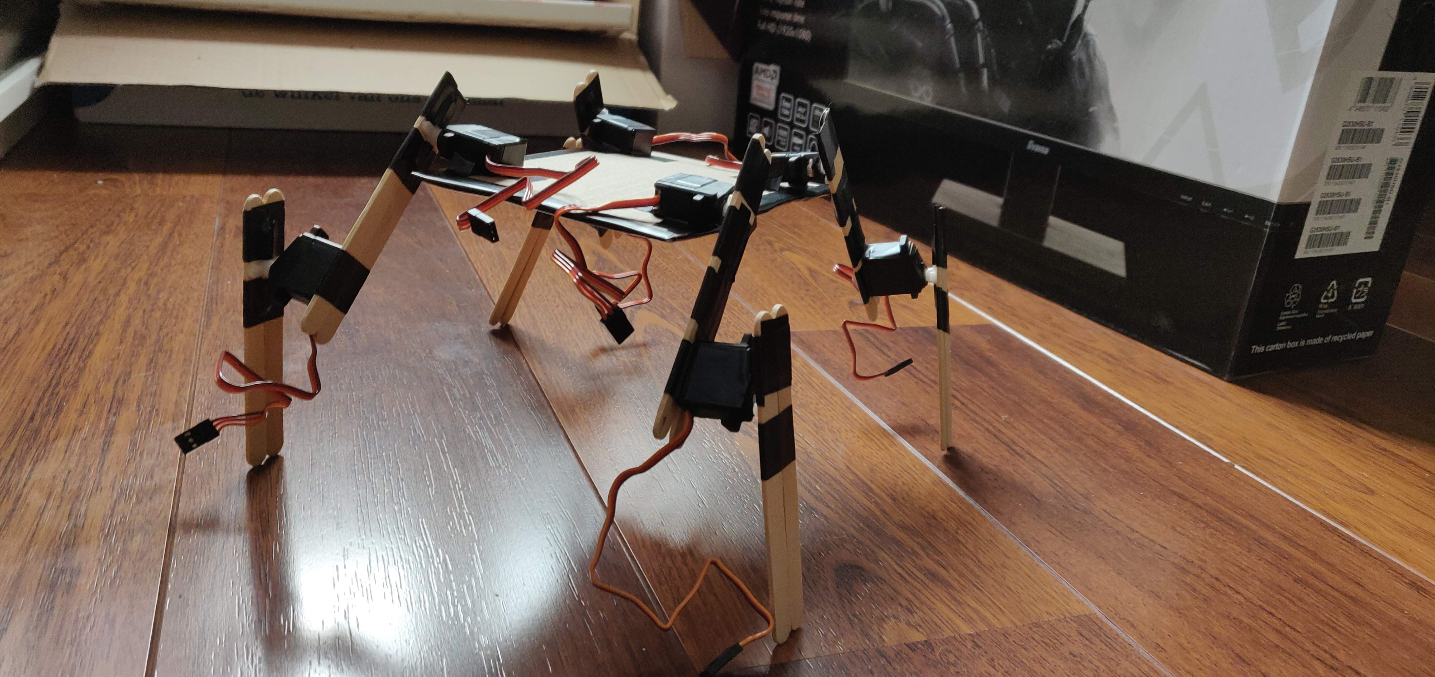
Prototype
Components
What I used to build Duke
- Raspberry Pi 4B – 4GB RAM
- Arduino Uno
- Arduino 16-channel PWM / Servo Shield
- Reely Micro-servo S-8246 Analoge servo
- Raspberry Pi Camera V2 video module
- Action powerbank
- Batterij pack – 4AA
- Usb cables
- Action music box
- Aux cable
- USB microphone
- Wooden sticks like those from an ice cream
- Cardboard
For the chassis
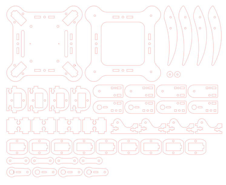
- mePed v2 design
- 40ea – M3 x 10mm Screws
- 16ea – M3 x 12mm Screws
- 24ea – M3 Hex Nuts
- 32ea – M3 Nyloc Hex Nuts
other option is ordering the kit from http://www.meped.io/mepedv2
Step 1: Making and assembling the hardware
First get you a dad like mine that is good in assembling hardware and can help you with this step. Then solder the Arduino 16-channel PWM together and test every input that exists on it.
After that eat a lot of ice creams and keep the wooden sticks, just kidding ;) . You can go and buy these wooden sticks at your local drug store, with these sticks and a piece of cardboard you can make your first prototype. With this prototype, you can test the form of your robot. Like if you want it like a spider, a cat, etc. it is best that you test it first before you officially make a design out of wood. Then add the servos at the places you want on the prototype and test them Arduino 16-channel PWM / Servo Shield up top attached on top of the Arduino.
Test it with this Arduino code:
#include <Adafruit_PWMServoDriver.h>

// called this way, it uses the default address 0x40
Adafruit_PWMServoDriver pwm = Adafruit_PWMServoDriver();
// you can also call it with a different address you want
//Adafruit_PWMServoDriver pwm = Adafruit_PWMServoDriver(0x41);
// you can also call it with a different address and I2C interface
//Adafruit_PWMServoDriver pwm = Adafruit_PWMServoDriver(0x40, Wire);

void setup() {
  Serial.begin(9600);
  Serial.println("GPIO test!");

  pwm.begin();
  pwm.setPWMFreq(1000);  // Set to whatever you like, we don't use it in this demo!

  // if you want to really speed stuff up, you can go into 'fast 400khz I2C' mode
  // some i2c devices dont like this so much so if you're sharing the bus, watch
  // out for this!
  Wire.setClock(400000);
}

void loop() {
  // Drive each pin in a 'wave'
  for (uint8_t pin=0; pin<16; pin++) {
    pwm.setPWM(pin, 4096, 0);       // turns pin fully on
    delay(100);
    pwm.setPWM(pin, 0, 4096);       // turns pin fully off
  }
}
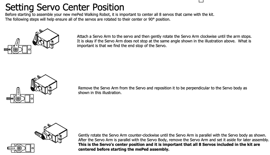
Make sure that every Servo is calibrated the right way or else you will get some weird movements! (picture 2) It can happen that your prototype is not strong enough to hold his own weight and move like it should be moving, this happened with my prototype. What I did was just make my official design but that’s a decision up to you. When you decide that you want to take your robot to the next level, you will need a laser cutter that cuts wood or order the mePed v2 kit. If you chose for the laser cutter you need to take the design of the mePed v2 (picture 3) and get the parts cut out, I used 3mm wood. After that you place everything in his place and assemble it together with the screws etc. Now you have your base chassis with servos etc. if you want more levels for placing your micro controllers on, like me, please feel free to build further at the hardware. Tip: to make sure the robot does not slip or fall while doing his tricks please attach some soft-anti slip footers at the base of his paws.
Step 2: The software
I want to control my robot, Duke, with my phone. I want Duke to walk forward, backward, left, right but I also want it to do some awesome tricks like wave, take a bow, kick away a ball, etc. While doing all that I also want to have a view from what Duke is doing, basically a camera on his eye level.
Camera
So that’s what we start with, testing out the Raspberry Pi Camera V2 video module with the tutorial of Raspberry Pi himself. https://projects.raspberrypi.org/en/projects/getting-started-with-picamera Then to integrate this camera view into the website, which will be build with HTML5 etc., we follow the tutorial of this guy; https://www.youtube.com/watch?v=5QAHlZoPlgI . He tells us exactly what we need to do to simply integrate the video in our HTML and explains everything, even gives us the needs for how to tweak the settings of the camera.
Arduino movement control
With the open source robot mePed v2 there not only the chassis available but also the code, http://www.meped.io/sites/default/files/2017-06/mePed_IR_Starter_Program_0.ino , this is written in C++. But between the mePed and Duke there are a lot of differences like the mePed is controlled by an IR Remote, they do not protect their Arduino with a Servo Shield but they use a Servo library instead, etc. So we need to rewrite their Arduino code to code that our Arduino + Servo Shield will understand. If you don’t have a lot of knowledge of Arduino code, it does not really matter, this is purely to understand the communication between Arduino and its components. We can’t use things like Servo.attach(PIN) and myServo.write(ANGLE) instead we need to set the PWM of the servo and then give it a pulse width to define the angle. After getting to know the code, understanding and modifying it to our application, you can start testing each movement on your own Duke. Our code:
#include <Adafruit_PWMServoDriver.h>

// called this way, it uses the default address 0x40
Adafruit_PWMServoDriver pwm = Adafruit_PWMServoDriver();

#define MIN_PULSE_WIDTH     650
#define MAX_PULSE_WIDTH     2350
#define DEFAULT_PULSE_WIDTH     1500
#define FREQUENCY     50

void setup() {
  //here you call a function like "center_servos()" and then your duke will do it
}

void center_servos(){
  pwm.setPWM(13, 0, pulseWidth(90));
  pwm.setPWM(15, 0, pulseWidth(90));
  pwm.setPWM(3, 0, pulseWidth(90));
  pwm.setPWM(1, 0, pulseWidth(90));
  pwm.setPWM(2, 0, pulseWidth(90));
  pwm.setPWM(0, 0, pulseWidth(90));
  pwm.setPWM(12, 0, pulseWidth(90));
  pwm.setPWM(14, 0, pulseWidth(90));
  Serial.println("servos centered");

  int s11 = 90; //front left pivot servo
  int s12 = 90; //front left lift servo
  int s21 = 90; //back left pivot servo
  int s22 = 90; //back left lift servo
  int s31 = 90; //back right pivot servo
  int s32 = 90; //back right lift servo
  int s41 = 90; //front right pivot servo
  int s42 = 90; //front right lift servo
 }

void lean_left(){
  pwm.setPWM(15, 0, pulseWidth(15));
  pwm.setPWM(1, 0, pulseWidth(15));
  pwm.setPWM(0, 0, pulseWidth(150));
  pwm.setPWM(14, 0, pulseWidth(150));
  Serial.println("lean_left done");
 }

void lean_right(){
  pwm.setPWM(15, 0, pulseWidth(150));
  pwm.setPWM(1, 0, pulseWidth(150));
  pwm.setPWM(0, 0, pulseWidth(15));
  pwm.setPWM(14, 0, pulseWidth(15));
  Serial.println("lean_right done");
 }

void wave(){
  center_servos();
  pwm.setPWM(1, 0, pulseWidth(45));
  pwm.setPWM(0, 0, pulseWidth(45));
  delay(200);
  pwm.setPWM(14, 0, pulseWidth(0));
  delay(200);
  pwm.setPWM(12, 0, pulseWidth(180));
  delay(200);
  pwm.setPWM(12, 0, pulseWidth(30));
  delay(300);
  pwm.setPWM(12, 0, pulseWidth(180));
  delay(300);
  pwm.setPWM(12, 0, pulseWidth(30));
  delay(300);
  pwm.setPWM(12, 0, pulseWidth(s41));
  delay(300);
  pwm.setPWM(12, 0, pulseWidth(s42));
  center_servos();
  Serial.println("wave done");
 }

void bow(){
  center_servos();
  delay(200);
  pwm.setPWM(15, 0, pulseWidth(15));
  pwm.setPWM(14, 0, pulseWidth(15));
  delay(700);
  pwm.setPWM(15, 0, pulseWidth(90));
  pwm.setPWM(14, 0, pulseWidth(90));
  delay(700);
  Serial.println("bow done");
 }


 void dance(){
  center_servos();
  delay(100);
  lean_left();
  delay(300);
  lean_right();
  delay(300);
  lean_left();
  delay(300);
  lean_right();
  delay(300);
  lean_left();
  delay(300);
  lean_right();
  delay(300);
  lean_left();
  delay(300);
  lean_right();
  delay(800);
  center_servos();
  delay(300);
  bow();
  center_servos();
 }


int pulseWidth(int angle){
  int pulse_wide, analog_value;
  pulse_wide = map(angle, 0, 180, MIN_PULSE_WIDTH, MAX_PULSE_WIDTH);
  analog_value = int(float(pulse_wide) / 1000000 * FREQUENCY * 4096);
  Serial.println(analog_value);
  return analog_value
}
Johnny-five movement control
Our control website is made out of HTML, CSS and JavaScript. Download the full code here https://github.com/EvaDenys99/PersonalProject . To control our movements with our phone, we can’t use the Arduino code therefor we need to transform our code to a code that is understandable for JavaScript to use. So that is where Johnny-five comes in, Johnny-five is an JavaScript Robotics & IoT Platform. Easy to implement and to use. Just install Johnny-five by using, in our case, yarn add Johnny-five. And then on the server side require the package and make a new board instance. After doing that we will need to declare the controller, which is our Arduino Adafruit Servo shield, the PCA9685. Here is an example of Johnny-five self; http://johnny-five.io/examples/servo-PCA9685/ . Now we can declare our servo's and the pins they connect to. Code examples:
const board = new five.Board({
  repl: false
});
const controller = "PCA9685";

// Servo myServo1; // Front Left Pivot Servo
  const FLPServo = new five.Servo({
    controller,
    pin: 13
  });
After turning the Arduino code into JavaScript code, we need to work on the communication as well. For this we are going to use Socket.io, we use this to trigger an event on our Arduino with our phone. To see the full code and inspect it go download it here; https://github.com/EvaDenys99/PersonalProject
Setting online on Raspberry Pi 4B
I have never used a Raspberry Pi before in my life, so as an extra I wanted it to be used on my robot Duke. It is only necessary for the eye of Duke, our camera live feed. So I decided to also use my Raspberry Pi as a host for the control website. Using FileZilla to headless connect to the Raspberry Pi, we just drop our code there. And voila our code is online and working or is it not? Because we used yarn it does not start up from itself. So the solution is adding a file start.sh, here you just add the line “node index.js” and if you don’t want to manually start the camera every time you can add that line of code too. Now our controls are online and working!
Step 3: Simple Alexa abilities
Some functionalities I want our Duke to have are things like play music, set timer, etc. Everything that an Alexa basically does, so I found us a working tutorial; https://developer.amazon.com/en-US/docs/alexa/alexa-voice-service/register-a-product.html . Not everything from it works because I live in Belgium, now I install my Action music box at the top of Duke, like some sort of hat. Then I connect it with an aux cable to my Raspberry Pi, as microphone I use an USB-microphone.
Step 4: Accessorize
Make your own Duke have a personality, make him pretty, etc. And enjoy your very own quadruped robot!

Prototype
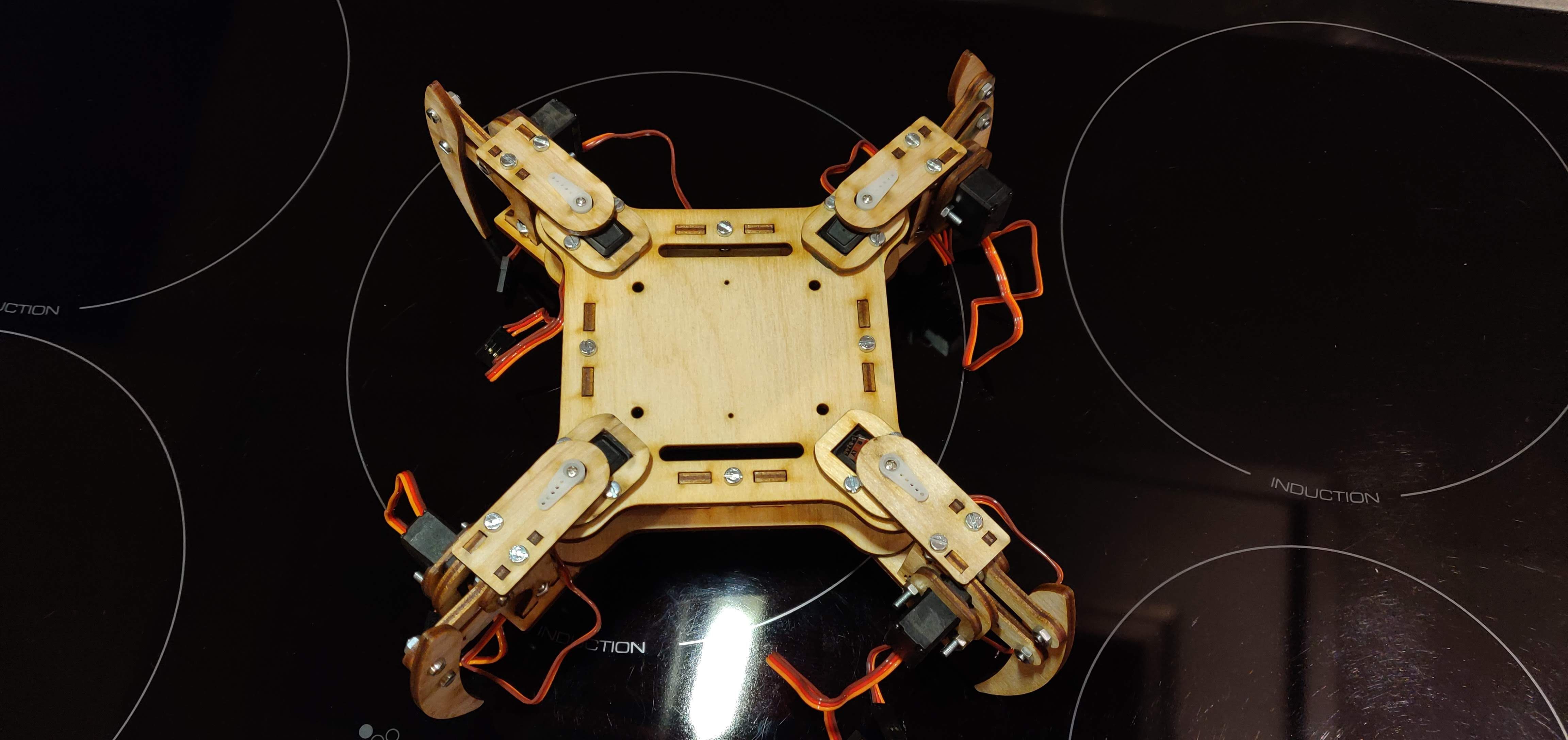
Body basis